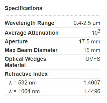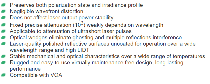
Laser Beam Attenuator 10PMA-1 utilizes the Fresnel reflection at uncoated flat front surfaces of two orthogonal optical wedges to pick off approximately 0.09% of the incoming beam. This attenuation device preserves both the irradiance profile and the polarization of the sampled beam. The 10PMA-1 may be used with either CW or Pulsed lasers to sample beams with diameters up to 15 mm and powers ranging from 10mW to 40W.
Possible Applications. Laser beam profiling using CCD based cameras, wavefront measurements with Shack-Hartmann sensors, spectral measurements with OSA.
Variable Optical Attenuators such as 10CWA168 can be combined with the 10PMA-1 to provide the additional fine attenuation.
The basic model containing uncoated Infrasil302 optical wedges can be modified to meet the requirements of a particular application. Various materials for optical wedges, fixed wavelength AR as well as BBAR coatings, mechanical adapters to fit customer's set up are available upon request.
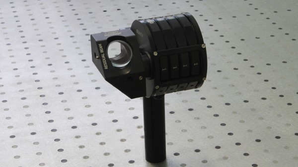
Principle of operation. The 10PMA-1 attenuator has four ports , "Input", "Sampled Beam", "Residual Beam" and "Port 4". Incoming beam with its optical axis orthogonal to the plane of the Input port is incident on the front flat surface of the first wedge at an angle of 45 arc deg and is partially1 reflected (reflection coefficient depends on the polarization state of incoming beam however does not exceed 0.1) toward the second wedge. The angle of incidence is again 45 arc deg while the second plane of incidence is orthogonal to the first one (the s-polarization now becomes p-polarization and vice versa). The latter fact allows the polarization state of the sampled beam to remain the same as of the incoming beam and to eliminate possible power instabilities caused by the fluctuation of the initial beam polarization state. The sampled beam emerges from the Sampled Beam port, its optical axis is shifted laterally by 15 mm and makes 90 arc deg angle with the optical axis of the incoming beam.
1More than 90% of incident light is transmitted through the 10PMA-1 so the appropriate beam-dumping device should be placed behind the Residual Beam port to ensure the safe operation of the sampler. Optical axis of the transmitted beam makes an angle of approx. 5 arc deg with the optical axis of the incoming beam.